From ArndaleBoard.org
Important Notice
THIS DOCUMENT
This work is licensed under the Creative Commons Attribution-Share Alike 3.0 Unported License.
To view a copy of this license, visit http://creativecommons.org/licenses/by-sa/3.0/ or send a letter to Creative Commons, 301, ACE High-en Tower 1st, Guro 3-dong, Guro-gu, Seoul, Korea.
For more information, see http://creativecommons.org/license/results-one?license_code=by-sa
This evaluation board/kit is intended for use for ENGINEERING DEVELOPMENT, DEMONSTRATION, OR EVALUATION PURPOSES ONLY and is not considered by arndale board to be a finished end-product fit for general consumer use.
WARRANTY
The Arndale Board is warranted against defects in materials and workmanship for a period of 90 days from purchase. This warranty does not cover any problems occurring as a result of improper use, modifications, exposure to water, excessive voltages, abuse, or accidents.
All boards will be returned via standard mail if an issue is found. If no issue is found or express return is needed, the customer will pay all shipping costs.
Getting Started with Andale Board / Arndale Board-K
Arndale Board Packages & Accessories
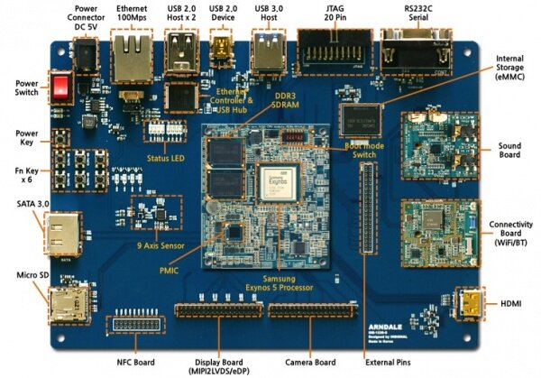
Arndale Board package is organized as follows.
Arndale Board Package
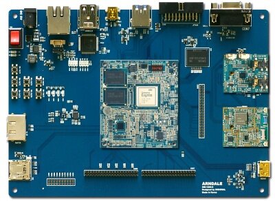
CPU Module & Baseboard Specifications
- Samsung Exynos 5 Dual Arndale Board
- CPU Board
- GHz dual core subsystem with 64/128 bit SIMD NEON
- 32KB(instruction)/32KB(DATA)L1 Cache and 1MB L2 Cache
- 32-bit 800Mhz DDR3(L)/DDR3 1Gbytes x 2
- Base Board
- Sensor
- Accelerator : Invensence MPU-6050
- Gyro : Invensence MPU-6050
- e-Compass : AKM -AK8963C
- ITU 601 camera Interface
- HDMI 1.4 interfaces with on-chip PHY
- One channel eDP output Single WQXGA
- MIPI DSI Standard Specification V1.01r11
- MIPI CSI standard Specification V1.0 Two ports
- USB3.0 Host or Device 1-channel that supports SS(5Gbps) with on-chip PHY
- USB2.0 Host or Device 1-channel that supports LS/FS/HS with on-chip PHY
- USB HSIC 2-channel that supports 480Mbps with on-chip PHY
- SATA 1.0/2.0/3.0 interface
- One channel eMMC 4.5
- One channel SDIO 3.0
- Two channel SD 2.0
- Four channel high-speed UART
(up to 3Mbps data rate for Bluetooth 2.0 EDR and IrDA 1.0SIR) - Three channel high-speed SPI
- Three channel 24-bit I2S audio interface
- Four channel I2C interface support , up 400kbps
- Four channel HS-I2C up to 3.1Mps
- Sensor
- CPU Board
Integrated Sensor Specifications
AKM -AK8963C e-Compass Sensor
- Si-monolithic 3-axis geomagnetic sensor LSI
- Measurement range : ± 4900 T
- Functions
- Time-sharing sequencer controls automatic measurement of 3-axis magnetism
- Built-in A to D converter for magnetometer data output
- 14-/16-bit digital output (selectable)
- Resolution:
- 0.6 T (14-bit)
- 0.15 T (16-bit)
- Individual adjustment data, already stored before shipment at AKM, such as sensitivity of sensor
- Serial interfaces (separated from main power supply, low voltage is acceptable)
- I2C-bus interface (can be operated at Standard- or Fast-mode)
- 4-wire SPI
- Operation modes: Power-down, Single measurement, Continuous measurement, External trigger measurement, Self test and ROM access
- Magnetic sensor overflow monitor function
- Power-on reset circuit and self test function
- Interrupt function for measurement data ready
- No clock input required (built-in oscillator)
- Automatic power-down function
- Operating temperature range : -30°C to +85°C
- Operating supply voltage range : Vdd = +2.4V to +3.6V, Vid = +1.65V to Vdd
- Current consumption
- Measurement (ave.) : 280 A (typ.) at 8 Hz repetition rate
- Power-down : 3 A (typ.)
- Packages : 14-pin WL-CSP, BGA (1.6  1.6  0.5 mm)
MPU-6050 Gyro & Accelerator Sensor
- Gyroscope Features
- Digital-output X-, Y-, and Z-Axis angular rate sensors (gyroscopes) with a user-programmable full-scale range of ±250, ±500, ±1000, and ±2000°/sec
- External sync signal connected to the FSYNC pin supports image, video and GPS synchronization
- Integrated 16-bit ADCs enable simultaneous sampling of gyros
- Enhanced bias and sensitivity temperature stability reduces the need for user calibration
- Improved low-frequency noise performance
- Digitally-programmable low-pass filter
- Gyroscope operating current: 3.6mA
- Standby current: 5μA
- Factory calibrated sensitivity scale factor
- User self-test
- Accelerometer Features
- Digital-output triple-axis accelerometer with a programmable full scale range of ±2g, ±4g, ±8g and ±16g
- Integrated 16-bit ADCs enable simultaneous sampling of accelerometers while requiring no external multiplexer
- Accelerometer normal operating current: 500μA
- Low power accelerometer mode current: 10μA at 1.25Hz, 20μA at 5Hz, 60μA at 20Hz, 110μA at 40Hz
- Orientation detection and signaling
- Tap detection
- User-programmable interrupts
- High-G interrupt
- User self-test
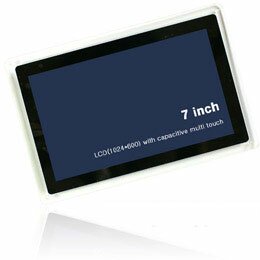
Display Module
- MIPI-DSI 4 Lane and eDP interface support
- 7 Inch TFT LCD, Resolution 1024 * 600
- Capacitive Touchscreen
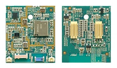
WiFi+BT+GPS Module
- Samsung SWB-A51H(WIFI,BT) + CSR GPS(G05t)
- WIFI + BT
- Vender : SEMCO
- Device name : SWB-A51H(ATHEROS AR6003) (JB mr1 not support)
- Features
- IEEE Std 802.11a/b/g, 802.11n(1x1)
- Bluetooth – Bluetooth specification Version 4.0 (BR/EDR+BLE)
- WiFi direct support
- Includes all the baseband and radio
- external antenna
- Low power consumption
- Cellular coexistence supported
- Host interfaces: SDIO
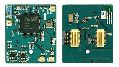
- GPS
- Vender : CSR
- Device Name : G05t
- Features
- GNSS, GLONASS, Galileo and SBAS reception for high GNSS availability. Galileo and Compass support via future software upgrade
- Host based MEMS enhancements for context recognition and improved accuracy
- Improved accuracy by reducing cross-correlation from strong signals and susceptibility to multipath
- High-sensitivity tracking to -165 dBm
- Selectable LO/IF options
- Excellent 3GPP acquisition and tracking margins
- Designed for simple coexistence with 2G and 3G radio systems
- Programmable I/O
- Integrated DSP for jamming immunity, handling CW, narrow band and wideband noise
WiFi+BT+GPS+FM Module (Arndale board-K / Upgrade package : JB mr1 support )
- Vender : MediaTek
- Device name : MT6620 4 in 1 combo
- Features
- IEEE Std 802.11a/b/g/n
- Dual band 2.4G/5G
- WiFi direct support
- SDIO 2.0 interface
- Bluetooth – BT v2.1+EDR / BT v3.0+HS(802.11AMP) compliance / BT v4.0 Low Energy
- FM over Bluetooth
- High speed UART interface(4Mbps), PCM
- GPS / A-GPS capability
- 165 dBm tracking sensitivity / 160 dBm hot start sensitivity / 148dBm cold /warm start sensitivity / UART interface
- FM : 76-108 MHz with 50KKHz step, RDS/RDMS support, UART, audio, digital audio interface(I2S)
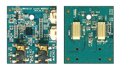
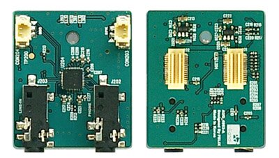
Audio Module
- Sound Codec : Wolfson WM1811A ( JB mr1 not support )
- Features
- 24-bit 2-channel Hi-fi DAC and 2-channel Hi-fi ADC
- 100dB SNR during DAC playback
- Smart MIC interface
- 2W stereo class D speaker drivers
- Capless Class W headphone drivers
- 4Line outputs (single-ended or differential)
- BTL Earpiece driver
- Digital audio interfaces for multi-processor architecture
- ReTune TM Mobile 5-band,4-channel parametic EQ
- Dynamic range controller
- Dual FLL provides all necessary clocks
- Active noise reduction circuits
- Intergrated LDO regulators
- Sound Codec : AsahiKASI AK4953(Arndale board-k / Upgrade Package : JB mr1 support)
- Feature
- 23-bit 96Khz 2-channel DAC and 2-channel ADC
- Digital De-emphasis Filter (tc=50/15μs, fs=32kHz, 44.1kHz, 48kHz)
- Digital ALC (Automatic Level Control)
- Digital Volume Control (+12dB ~ ?115dB, 0.5dB Step, Mute)
- Capacitor-less Stereo Headphone Amplifier
- HP-Amp Performance: S/(N+D): 80dB@24mW, S/N: 96dB
- Output Power: 24mW@16Ω
- Pop Noise Free at Power-ON/OFF
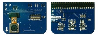
Camera Module
- MIPI-CSI and ITU601 interface support
- 5M Pixel Camera
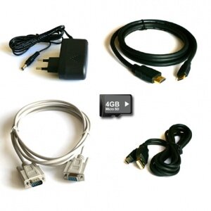
Accessories
- AC Adapter (5V 5A)
- SATA SSD120GB or 240GB (Sata To USB 3.0 cable or SATA cable + Power cable)
- HDMI, Serial, USB Cable, SD Card, etc
Detail of Arndale Board
Connection Guide
Host Environment for Android
First of all, there is a need host PC to build android. The host PC recommended installed linux or mac os.
- We recommend that you use Ubuntu Linux. Ubuntu 10.10 will use to explain about the below.
- Build environments tested various platform of ubuntu distributions. But as we mentioned, we recommended ubuntu 10.10 because it is the best solution until now.
- To build ICS(IceCream Sandwitch) or higher version, You must install based on 64bit host system.
Installing required packages (Ubuntu 10.04 -- 11.10)
You will need a 64-bit version of Ubuntu. Ubuntu 10.04 is recommended. Building using a newer version of Ubuntu is currently only experimentally supported and is not guaranteed to work on branches other than master.
$ sudo apt-get install git-core gnupg flex bison gperf build-essential \
  zip curl zlib1g-dev libc6-dev lib32ncurses5-dev ia32-libs \
 x11proto-core-dev libx11-dev lib32readline5-dev lib32z-dev \
 libgl1-mesa-dev g++-multilib mingw32 tofrodos python-markdown \
 libxml2-utils xsltproc
On Ubuntu 10.10
$ sudo ln -s /usr/lib32/mesa/libGL.so.1 /usr/lib32/mesa/libGL.
On Ubuntu 11.10
$ sudo apt-get install libx11-dev:i386
Installing required packages (Ubuntu 12.04)
Building on Ubuntu 12.04 is currently only experimentally supported and is not guaranteed to work on branches other than master.
sudo apt-get install git-core gnupg flex bison gperf build-essential \
  zip curl libc6-dev libncurses5-dev:i386 x11proto-core-dev \
  libx11-dev:i386 libreadline6-dev:i386 libgl1-mesa-glx:i386 \
  libgl1-mesa-dev g++-multilib mingw32 openjdk-6-jdk tofrodos \
  python-markdown libxml2-utils xsltproc zlib1g-dev:i386
$ sudo ln -s /usr/lib/i386-linux-gnu/mesa/libGL.so.1 /usr/lib/i386-linux-gnu/libGL.so
Configuring USB Access
Under GNU/linux systems (and specifically under Ubuntu systems), regular users can't directly access USB devices by default. The system needs to be configured to allow such access.
The recommended approach is to create a file /etc/udev/rules.d/51-android.rules (as the root user) and to copy the following lines in it.
# adb protocol on passion (Nexus One)
SUBSYSTEM=="usb", ATTR{idVendor}=="18d1", ATTR{idProduct}=="4e12", MODE="0600", OWNER=""
# fastboot protocol on passion (Nexus One)
SUBSYSTEM=="usb", ATTR{idVendor}=="0bb4", ATTR{idProduct}=="0fff", MODE="0600", OWNER=""
# adb protocol on crespo/crespo4g (Nexus S)
SUBSYSTEM=="usb", ATTR{idVendor}=="18d1", ATTR{idProduct}=="4e22", MODE="0600", OWNER=""
# fastboot protocol on crespo/crespo4g (Nexus S)
SUBSYSTEM=="usb", ATTR{idVendor}=="18d1", ATTR{idProduct}=="4e20", MODE="0600", OWNER=""
# adb protocol on stingray/wingray (Xoom)
SUBSYSTEM=="usb", ATTR{idVendor}=="22b8", ATTR{idProduct}=="70a9", MODE="0600", OWNER=""
# fastboot protocol on stingray/wingray (Xoom)
SUBSYSTEM=="usb", ATTR{idVendor}=="18d1", ATTR{idProduct}=="708c", MODE="0600", OWNER=""
# adb protocol on maguro/toro (Galaxy Nexus)
SUBSYSTEM=="usb", ATTR{idVendor}=="04e8", ATTR{idProduct}=="6860", MODE="0600", OWNER=""
# fastboot protocol on maguro/toro (Galaxy Nexus)
SUBSYSTEM=="usb", ATTR{idVendor}=="18d1", ATTR{idProduct}=="4e30", MODE="0600", OWNER=""
# adb protocol on panda (PandaBoard)
SUBSYSTEM=="usb", ATTR{idVendor}=="0451", ATTR{idProduct}=="d101", MODE="0600", OWNER=""
# fastboot protocol on panda (PandaBoard)
SUBSYSTEM=="usb", ATTR{idVendor}=="0451", ATTR{idProduct}=="d022", MODE="0600", OWNER=""
# usbboot protocol on panda (PandaBoard)
SUBSYSTEM=="usb", ATTR{idVendor}=="0451", ATTR{idProduct}=="d00f", MODE="0600", OWNER=""
# usbboot protocol on panda (PandaBoard ES)
SUBSYSTEM=="usb", ATTR{idVendor}=="0451", ATTR{idProduct}=="d010", MODE="0600", OWNER=""
# adb protocol on grouper (Nexus 7)
SUBSYSTEM=="usb", ATTR{idVendor}=="18d1", ATTR{idProduct}=="4e42", MODE="0600", OWNER=""
# fastboot protocol on grouper (Nexus 7)
SUBSYSTEM=="usb", ATTR{idVendor}=="18d1", ATTR{idProduct}=="4e40", MODE="0600", OWNER=""
Those new rules take effect the next time a device is plugged in. It might therefore be necessary to unplug the device and plug it back into the computer.
- After you modify, the udev rules will be activated with restarting Host PC or "sudo udevadm control --reload-rules" command.
Environment for Bootloader/Kernel Build
- Download toolchain GCC Version 4.4.1 (Sourcery G++ Lite 2009q3, "arm-2009q3.tar.gz") from Developers Forum of Insignal
- Unzip the downloaded toolchain into /your/own/directory/ (ex> /usr/local/arm-2009q3)
- Set the toolchain path up to your PATH environment like ‘export PATH=$PATH:/your/own/directory’ (ex> export PATH=$PATH:/usr/local/arm-2009q3/bin)
Installing the JDK
Installing Java6
Please download from Oracle web site and select JDK(Java SE 6 Update 3X).
Download 64bit type
- Download "Linux x64 (64bit)" jdk6u3X-linux-x64.bin
Run "jdk6u3X-linux-x64.bin" in download folder
$ cd ~/download
$ chmod +x jdk-6u3X-linux-x64.bin
$ ./jdk-6u3X-linux-x64.bin
Move to ~'/apps/'
$ mkdir -p ~/apps
$ mv jdk1.6.0_3X ~/apps/
Make symbolic link
$ ln -s ~/apps/jdk1.6.0_3X ~/apps/jdk1.6
Add below commands in '.bashrc'
export JAVA_HOME=~/apps/jdk1.6
export ANDROID_JAVA_HOME=$JAVA_HOME
export PATH=$JAVA_HOME/bin/:$PATH
Checking JAVA Version
$ which java
/home/'(User)'/apps/jdk1.6/bin//java
$ java -version
java version "1.6.0_3X"
Java(TM) SE Runtime Environment (build 1.6.0_3X-b04)
Java HotSpot(TM) 64-Bit Server VM (build 20.9-b04, mixed)
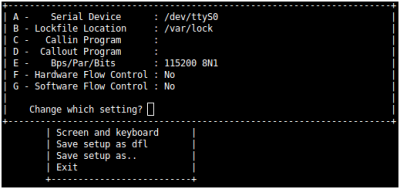
Setting serial port
- Serial Port : comX ( X : means your connected) /dev
- Baud Rate : 115200
- Parity : 8bit
- Hardware Flow Control : No
- Stop bit : 1bit
How to Download Source Tree
Installing Repo
Repo is a tool that makes it easier to work with Git in the context of Android. For more information about Repo, see Version Control.
To install, initialize, and configure Repo, follow these steps:
- Make sure you have a bin/ directory in your home directory, and that it is included in your path:
$ mkdir ~/bin
$ PATH=~/bin:$PATH
- Download the Repo script and ensure it is executable:
$ curl https://dl-ssl.google.com/dl/googlesource/git-repo/repo > ~/bin/repo
$ chmod a+x ~/bin/repo
- For version 1.17, the SHA-1 checksum for repo is ddd79b6d5a7807e911b524cb223bc3544b661c28
Initializing a Repo client
After installing Repo, set up your client to access the android source repository:
- Create an empty directory to hold your working files. If you're using MacOS, this has to be on a case-sensitive filesystem. Give it any name you like:
$ mkdir WORKING_DIRECTORY
$ cd WORKING_DIRECTORY
- Run repo init to bring down the latest version of Repo with all its most recent bug fixes. You must specify a URL for the manifest, which specifies where the various repositories included in the Android source will be placed within your working directory.
$ repo init -u git://git.insignal.co.kr/samsung/exynos/android/manifest.git -b jb
- To check out a branch other than "jb", specify it with -b:
$ repo init -u git://git.insignal.co.kr/samsung/exynos/android/manifest.git -b jb-mr1
- To check out a branch other than "jb mr1", specify it with -b:
- jb mr-1 not support WM1811(sound) module and A51H(connectvity) module
A successful initialization will end with a message stating that Repo is initialized in your working directory. Your client directory should now contain a .repo directory where files such as the manifest will be kept.
Getting the files
To pull down files to your working directory from the repositories as specified in the default manifest, run
$ repo sync
The Android source files will be located in your working directory under their project names. The initial sync operation will take an hour or more to complete. For more about repo sync and other Repo commands, see Version Control.
Download proprietary for Eyxnos5250
Download proprietary archive, vendor_samsung_slsi_exynos5250_20121107_xxxxxx.run to root of android source tree.
Make it executable and run it:
$ chmod +x vendor_samsung_slsi_exynos5250_20121107_xxxxxx.run
$ ./vendor_samsung_slsi_exynos5250_20121107_xxxxxx.run
Download proprietary archive for other peripherals, vendor_insignal_arndale_xxxxxxxx_xxxxxxx.run to root of android source tree.
Make it executable and run it:
$ chmod +x vendor_insignal_arndale_xxxxxxxx_xxxxxxx.run
$ ./vendor_insignal_arndale_xxxxxxxx_xxxxxxx.run
It show license of it's contents. After agree it by typing "I ACCEPT", proprietary files will be extracted under vendor/samsung_slsi/exynos5250/
Building the System
The basic sequence of build commands is as follows:
Initialize
- Initialize the environment with the envsetup.sh script. Note that replacing "source" with a single dot saves a few characters, and the short form is more commonly used in documentation.
$ source ./arndale_envsetup.sh
or
$ . ./arndale_envsetup.sh
- Environment initialization is complete, the following message appears.
including device/generic/armv7-a-neon/vendorsetup.sh
including device/generic/armv7-a/vendorsetup.sh
including device/samsung/arndale/vendorsetup.sh
including device/samsung/smdk5250/vendorsetup.sh
including sdk/bash_completion/adb.bash
============================================
PLATFORM_VERSION_CODENAME=REL
PLATFORM_VERSION=4.1.1
TARGET_PRODUCT=full_arndale
TARGET_BUILD_VARIANT=eng
TARGET_BUILD_TYPE=release
TARGET_BUILD_APPS=
TARGET_ARCH=arm
TARGET_ARCH_VARIANT=armv7-a-neon
HOST_ARCH=x86
HOST_OS=linux
HOST_OS_EXTRA=Linux-3.0.0-26-generic-x86_64-with-Ubuntu-11.10-oneiric
HOST_BUILD_TYPE=release
BUILD_ID=JRO03R
OUT_DIR=out
============================================
FYI: use following addtional functions to easy-to-build
- fuse_uboot:         Make bootalbe SD (which only has u-boot)
- fastboot_all:       Flash kernel, ramdisk, system via fastboot
- fastboot_reset:     Erase userdata and cache via fastboot
- fastboot_fmt_sd:    Erase SDCard via fastboot
- kernel_make:        Make kernel
- mkgrep:             Grep *.mk like jgrep
How to change the BUILD_VARIANT and BUILD_TYPE
- Change the TARGET_BUILD_VARIANT, do the following:
$ choosevariant
the following message appears.
Variant choices are:
     1. user
     2. userdebug
     3. eng
Which would you like? [eng]
- Change the TARGET_BUILD_TYPE do the following:
$ choosetype
the following message appears.
Build type choices are:
     1. release
     2. debug
Which would you like? [1]
Using ccache
ccache is a compiler cache for C and C++ that can help make builds faster. In the root of the source tree, do the following:
- On ICS
$ export USE_CCACHE=1
$ export CCACHE_DIR=//.ccache
$ prebuilts/linux-x86/ccache/ccache -M 20G
- On JB
$ export USE_CCACHE=1
$ export CCACHE_DIR=//.ccache
$ prebuilts/misc/linux-x86/ccache/ccache -M 20G
You can watch ccache being used by doing the following:
$ watch -n1 -d prebuilts/misc/linux-x86/ccache/ccache -s
On OSX, you should replace linux-x86 with darwin-x86.
Build the Code
Build everything with make. GNU make can handle parallel tasks with a -jN argument, and it's common to use a number of tasks N that's between 1 and 2 times the number of hardware threads on the computer being used for the build. E.g. on a dual-E5520 machine (2 CPUs, 4 cores per CPU, 2 threads per core), the fastest builds are made with commands between make -j16 and make -j32.
Building the Bootloader
You should be use following cross-compiler to build the boot loader.
$ cd < WORKING_DIRECTORY>/u-boot/
$ make clobber
$ make ARCH=arm CROSS_COMPILE=arm-none-linux-gnueabi- arndale_config
$ make ARCH=arm CROSS_COMPILE=arm-none-linux-gnueabi-
After the build, < WORKING_DIRECTORY>/uboot.bin is being made available.
Building the Kernel
Setting up Arndale Board’s configuration. and after build.
$ kernel_make distclean
$ kernel_make arndale_android_defconfig
$ kernel_make -j16
- If you buy arndaleboard from pyrustek
$ kernel_make distclean
$ kernel_make pyrustek_arndale_android_defconfig
$ kernel_make -j16
If you want to use the kernel menuconfig, type the following command.
$ kernel_make arndale_android_defconfig
$ kernel_make menuconfig
- If you buy arndaleboard from pyrustek
$ kernel_make pyrustek_arndale_android_defconfig
$ kernel_make menuconfig
Building the Android
- Before building Android, you must build Kernel. Otherwise, you can cause unexpected building problems.
$ make kernel-binaries
$ make -j4
- If you buy ArndaleBoard from pyrustek, modify vendor/insignal/arndale/device-vendor.mk like below
#$(call inherit-product-if-exists,vendor/insignal/arndale/mpu6050/mpu6050-vendor.mk)
- Before building Android, you must build Kernel. Otherwise, you can cause unexpected building problems.
$ make kernel-binaries
$ make -j4
Please run 'make kernel-binaries' without -j option
Building fastboot and adb
If you don't already have those tools, fastboot and adb can be built with the regular build system. Follow the instructions on the page about building, and replace the main make command with
$ make fastboot adb
Build code for SD/MMC boot
device/samsung/arndale/conf/vold.fstab
   * Change the sdcard0 and sdcard1 lines so that the first line is sdcard1 and the second is sdcard0.
device/samsung/arndale/conf/fstab.arndale
   * Change all references to mmcblk0px to mmcblk1px.
device/samsung/arndale/conf/init.arndale.rc
   * Change the 2 references to mmcblk0px to mmcblk1px.
system/core/rootdir/etc/mountd.conf
   * Change the reference to mmcblk0 to mmcblk1
How to Flash a Device
Download Environment
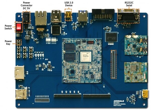
To download an image to the target system, USB and Serial port connections are needed. USB and serial ports are connected as shown in the following pictures:
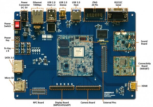
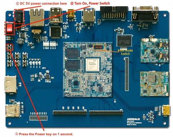
Boot mode setup
Arndale board provides two types of boot mode. And eMMC is the default boot mode.
- eMMC bootmode (It's default bootmode)
- DIP switch(CFG1/SW1) CFG1[6:1] : 101000
- SD/MMC bootmode (Use SD/MMC bootmode when eMMC bootmode has unstable.)
- DIP switch(CFG1/SW1) CFG1[6:1] : 000100
Turn on the target system
Turn the power key, press the keys shown in the following pictures on 1 second.The board will work.
Download software on target system
When booting the board, press any key(of HostPC Keyboard, focused on serial terminal program window) in 3 seconds for enter the u-boot command mode.
OOK


U-Boot 2010.12 (Oct 11 2012 - 18:54:08) for Insignal Arndale


CPU: S5PC520 Rev1.0 [Samsung SOC on SMP Platform Base on ARM CortexA15]
APLL = 1400MHz, MPLL = 800MHz, EPLL = 96MHz, VPLL = 300MHz, BPLL = 666MHz
DRAM:  2047 MiB


TrustZone Enabled BSP
BL1 version:
PMIC: S5M8767


Checking Boot Mode ... EMMC4.41
REVISION: 1.0
REVISION: 1.0
NAME: S5P_MSHC0
MMC Device 0: 3816 MB
MMC Device 1: 0 MB
MMC Device 2 not found
*** Warning - using default environment


Hit any key to stop autoboot:  0
Arndale #
- Type the 'fastboot' command on bootloader. the following message appears. and Enter into the download mode.
Arndale # fastboot


[Partition table on MoviNAND]
ptn 0 name='fwbl1' start=0x2 len=N/A (use hard-coded info. (cmd: movi))
ptn 1 name='bl2' start=N/A len=N/A (use hard-coded info. (cmd: movi))
ptn 2 name='bootloader' start=N/A len=N/A (use hard-coded info. (cmd: movi))
ptn 3 name='tzsw' start=N/A len=N/A (use hard-coded info. (cmd: movi))
ptn 4 name='kernel' start=N/A len=N/A (use hard-coded info. (cmd: movi))
ptn 5 name='ramdisk' start=N/A len=0x0(~27262976KB) (use hard-coded info. (cmd: movi))
ptn 6 name='system' start=0x2 len=0x0(~512065536KB)
ptn 7 name='userdata' start=0x2 len=0x0(~512032768KB)
ptn 8 name='cache' start=0x2 len=0x0(~512032768KB)
ptn 9 name='fat' start=0x2 len=0x0(~-1845690368KB)
OTG cable Connected!
Flash the Bootloader
Enter the following command from the host system.
$ sudo fastboot flash bootloader < WORKING_DIRECTORY>/u-boot/u-boot.bin
Flash the Kernel
Enter the following command from the host system.
$ sudo fastboot flash kernel/kernel/arch/arm/boot/zImage
Flash the Android System
Enter the following command from the host system.
- Flash the Android Ramdisk image.
$ sudo fastboot flash ramdisk/out/target/product/arndale/ramdisk.img.ub
- Flash the Android System image.
$ sudo fastboot flash system/out/target/product/arndale/system.img
- Erase Android Userdata.
$ sudo fastboot erase userdata
- Erase Android Cache
$ sudo fastboot erase cache
Launch Android!
Enter the following command to boot now.
$ sudo fastboot reboot
Appendix
eMMC boot loader repair guide
There is need to repair eMMC bootloader when have some trouble. In that case, you can use below sequence.
Prepared micro SD/MMC for ARNDALE bootable.
Prepare below image files.
- BL1 is a binary for firmware supported by manufacturer.
- It's located at
/vendor/insignal/arndale/exynos5250/exynos5250.bl1.bin
- It's located at
- BL2 is a binary for Second Bootloader.
- It's generated u-boot build in
.
- It's generated u-boot build in
- tzsw.img is a binary for TrustZone Software
- It's located at
/vendor/insignal/arndale/exynos5250/exynos5250.tzsw.bin
- It's located at
- u-boot.bin is a U-Boot
- It's generated u-boot build in
.
- It's generated u-boot build in
Connect micro SD/MMC in your host machine and check device name.
$ sudo fdisk -l
   Device Boot      Start         End      Blocks   Id  System
    /dev/sdc1               1        1809         b  W95 FAT32
Flash image to SD/MMC via fusing script.
$ source ./arndale_envsetup.sh
$ mksdboot /dev/sdc
Bootmode setup android
- NOTICE1
- On first time turn on ARNDALE board, it's empty state.
It will be work slow, because running secondary boot.
(First, failed eMMC boot Second, try to SD/MMC boot).
You'll be need boot from SD/MMC for download and flash software on eMMC.
After software download and flash on eMMC, You can boot from eMMC for ARNDALE.
- On first time turn on ARNDALE board, it's empty state.
- Check eMMC boot mode
- Check eMMC boot mode on DIP switch(CFG1/SW1) for download and flash software on eMMC.
- Check eMMC boot mode on DIP switch(CFG1/SW1) for download and flash software on eMMC.
Partion split and format
Insert the SD card and turn it on. When booting the board, press any key in 3 seconds for enter the u-boot command mode. (it takes about 10 sec.)
OOK


U-Boot 2010.12 (Oct 11 2012 - 18:54:08) for Insignal Arndale


CPU: S5PC520 Rev1.0 [Samsung SOC on SMP Platform Base on ARM CortexA15]
APLL = 1400MHz, MPLL = 800MHz, EPLL = 96MHz, VPLL = 300MHz, BPLL = 666MHz
DRAM:  2047 MiB


TrustZone Enabled BSP
BL1 version:
PMIC: S5M8767


Checking Boot Mode ... EMMC4.41
REVISION: 1.0
REVISION: 1.0
NAME: S5P_MSHC0
MMC Device 0: 3816 MB
MMC Device 1: 0 MB
MMC Device 2 not found
*** Warning - using default environment


Hit any key to stop autoboot:  0
Arndale #
- Type the below commands on bootloader for eMMC partition split
#] fdisk -c 0 520 520 520
- Type the below commands on bootloader for partition format
#] fatformat mmc 0:1
#] ext3format mmc 0:2
#] ext3format mmc 0:3
#] ext3format mmc 0:4
Download & flash software to eMMC
Will be need below image file for download and flash, Prepare below image files.
- BL1 is a binary for firmware supported by manufacturer.
- It's located at
/vendor/insignal/arndale/exynos5250/exynos5250.bl1.bin
- It's located at
- BL2 is a binary for Second Bootloader.
- It's generated u-boot build in
.
- It's generated u-boot build in
- tzsw.img is a binary for TrustZone Software
- It's located at
/vendor/insignal/arndale/exynos5250/exynos5250.tzsw.bin
- It's located at
- u-boot.bin is a U-Boot
- It's generated u-boot build in
.
- It's generated u-boot build in
`fastboot` command execute for download images and writing.
#] fastboot
`fastboot` command execute on your host machine.
- bootloader & bootable images
$ fastboot flash fwbl1 exynos5250.bl1.img
$ fastboot flash bl2 bl2.bin
$ fastboot flash bootloader u-boot.bin
$ fastboot flash tzsw exynos5250.tzsw.img
- linux kernel
$ fastboot flash kernel zImage
- Android
$ fastboot flash ramdisk ramdisk.img.ub
$ fastboot flash system system.img
How to use SD/MMC boot
You want to use SD/MMC Boot mode(ex. eMMC boot unstable) you can use below sequence.
Prepared micro SD/MMC for ARNDALE bootable.
Prepare below image files.
- BL1 is a binary for firmware supported by manufacturer.
- It's located at
/vendor/insignal/arndale/exynos5250/exynos5250.bl1.bin
- It's located at
- BL2 is a binary for Second Bootloader.
- It's generated u-boot build in
.
- It's generated u-boot build in
- tzsw.img is a binary for TrustZone Software
- It's located at
/vendor/insignal/arndale/exynos5250/exynos5250.tzsw.bin
- It's located at
- u-boot.bin is a U-Boot
- It's generated u-boot build in
.
- It's generated u-boot build in
Connect micro SD/MMC in your host machine and check device name.
$ sudo fdisk -l
   Device Boot      Start         End      Blocks   Id  System
    /dev/sdc1               1        1809         b  W95 FAT32
Flash image to SD/MMC via fusing script.
$ source ./arndale_envsetup.sh
$ mksdboot /dev/sdc
Change Boot mode
Check SD/MMC boot mode on DIP switch(CFG1/SW1) for download and flash software on SD/MMC.
Partion split and format
Insert the SD card and turn it on. When booting the board, press any key in 3 seconds for enter the u-boot command mode. (it takes about 10 sec.)
OOK


U-Boot 2010.12 (Oct 11 2012 - 18:54:08) for Insignal Arndale


CPU: S5PC520 Rev1.0 [Samsung SOC on SMP Platform Base on ARM CortexA15]
APLL = 1400MHz, MPLL = 800MHz, EPLL = 96MHz, VPLL = 300MHz, BPLL = 666MHz
DRAM:  2047 MiB


TrustZone Enabled BSP
BL1 version:
PMIC: S5M8767


Checking Boot Mode ... EMMC4.41
REVISION: 1.0
REVISION: 1.0
NAME: S5P_MSHC0
MMC Device 0: 3816 MB
MMC Device 1: 0 MB
MMC Device 2 not found
*** Warning - using default environment


Hit any key to stop autoboot:  0
Arndale #
- Type the below commands on bootloader for eMMC partition split
#] emmc open 0
#] fdisk -c 0 520 520 520
#] emmc close 0
- Type the below commands on bootloader for partition format
#] fatformat mmc 0:1
#] ext3format mmc 0:2
#] ext3format mmc 0:3
#] ext3format mmc 0:4
Download & flash software to eMMC
- Will be need below image file for download and flash.
- bl1 : exynos5250.bl1.bin
- bl2 : bl2.bin
- tzsw : exynos5250.tzsw.bin
- bootloader : u-boot.bin
- linux kernel : zImage
- ramdisk : ramdisk.img.ub
- system : system.img
- `fastboot` command execute for downlaod images and writing.
#] fastboot
`fastboot` command execute on your host machine.
- bootloader & bootable images
$ fastboot flash fwbl1 exynos5250.bl1.bin
$ fastboot flash bl2 bl2.bin
$ fastboot flash bootloader u-boot.bin
$ fastboot flash tzsw exynos5250.tzsw.bin
- linux kernel
$ fastboot flash kernel zImage
- Android
$ fastboot flash ramdisk ramdisk.img.ub
$ fastboot flash system system.img
How to flash bootloader in SD/MMC to eMMC
There is need to erase eMMC toreset because have some trouble or you want to back SD Booting mode. In that case, you can use below sequence.
- Change Dip switch(CFG1/SW1) 1, 3 to SD Boot mode.
- Insert Bootable SDCard, then enter u-boot command mode.
- Type below command on U-Boot command mode.
mmc erase boot 1 0 4000
mmc erase user 1
- mmc erase boot 1 0 4000 : eMMC boot area initialize.
- mmc erase user 1 0 : eMMC kernel ramdisk area initialize
Flash bootloader in SD/MMC card to EMMC
If you need to download in EMMC from SD card boot image. See the following items:
- When used to boot SD card and boot mode was that 1st. EMMC, 2nd. SDCARD.
- Download the boot loader on the EMMC from SD card.
- The following instructions are from the boot loader command line.
#] emmc open 0
#] movi read fwbl1 ; movi write zero fwbl1
#] movi read bl2 ; movi write zero bl2
#] movi read u-boot ; movi write zero u-boot
#] movi read tzsw ; movi write zero tzsw
#] emmc close 0
- When used to boot SD card and boot mode was that 1st. SDCARD, 2nd, EMMC
- Download the boot loader on the EMMC from SD card.
- The following instructions are from the boot loader command line.
#] emmc open 1
#] movi read fwbl1 ; movi write zero fwbl1
#] movi read bl2 ; movi write zero bl2
#] movi read u-boot ; movi write zero u-boot
#] movi read tzsw ; movi write zero tzsw
#] emmc close 1
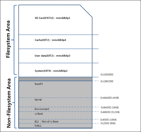
SD Card Partition Map
How to build ARM DS-5 gator driver
- Initialize the environment with the envsetup.sh script. Note that replacing "source" with a single dot saves a few characters, and the short form is more commonly used in documentation.
$ source ./arndale_envsetup.sh
or
$ . /arndale_envsetup.sh
- Environment initialization is complete, the following message appears.
including device/generic/armv7-a-neon/vendorsetup.sh
including device/generic/armv7-a/vendorsetup.sh
including device/samsung/arndale/vendorsetup.sh
including device/samsung/smdk5250/vendorsetup.sh
including sdk/bash_completion/adb.bash
============================================
PLATFORM_VERSION_CODENAME=REL
PLATFORM_VERSION=4.1.1
TARGET_PRODUCT=full_arndale
TARGET_BUILD_VARIANT=eng
TARGET_BUILD_TYPE=release
TARGET_BUILD_APPS=
TARGET_ARCH=arm
TARGET_ARCH_VARIANT=armv7-a-neon
HOST_ARCH=x86
HOST_OS=linux
HOST_OS_EXTRA=Linux-3.0.0-26-generic-x86_64-with-Ubuntu-11.10-oneiric
HOST_BUILD_TYPE=release
BUILD_ID=JRO03R
OUT_DIR=out
============================================
FYI: use following addtional functions to easy-to-build
- fuse_uboot:         Make bootalbe SD (which only has u-boot)
- fastboot_all:       Flash kernel, ramdisk, system via fastboot
- fastboot_reset:     Erase userdata and cache via fastboot
- fastboot_fmt_sd:    Erase SDCard via fastboot
- kernel_make:        Make kernel
- mkgrep:             Grep *.mk like jgrep
- Change the ARM DS-5 gactor driver directory, do the following:
$ cd /hardware/arm/gator/gator-driver
- Build the Code
$ make clean
$ kernel_make -C $TOP/kernel M=$PWD modules
- Turn on the target system and boot is complete, do the following:
$ adb remount
$ adb push gator.ko /system/modules
How to build MTK MT6620(CT9000 Module) driver
- Initialize the environment with the envsetup.sh script. Note that replacing "source" with a single dot saves a few characters, and the short form is more commonly used in documentation.
$ source ./arndale_envsetup.sh
or
$ . /arndale_envsetup.sh
- Environment initialization is complete, the following message appears.
including device/generic/armv7-a-neon/vendorsetup.sh
including device/generic/armv7-a/vendorsetup.sh
including device/samsung/arndale/vendorsetup.sh
including device/samsung/smdk5250/vendorsetup.sh
including sdk/bash_completion/adb.bash
============================================
PLATFORM_VERSION_CODENAME=REL
PLATFORM_VERSION=4.1.1
TARGET_PRODUCT=full_arndale
TARGET_BUILD_VARIANT=eng
TARGET_BUILD_TYPE=release
TARGET_BUILD_APPS=
TARGET_ARCH=arm
TARGET_ARCH_VARIANT=armv7-a-neon
HOST_ARCH=x86
HOST_OS=linux
HOST_OS_EXTRA=Linux-3.0.0-26-generic-x86_64-with-Ubuntu-11.10-oneiric
HOST_BUILD_TYPE=release
BUILD_ID=JRO03R
OUT_DIR=out
============================================
FYI: use following addtional functions to easy-to-build
- fuse_uboot:         Make bootalbe SD (which only has u-boot)
- fastboot_all:       Flash kernel, ramdisk, system via fastboot
- fastboot_reset:     Erase userdata and cache via fastboot
- fastboot_fmt_sd:    Erase SDCard via fastboot
- kernel_make:        Make kernel
- mkgrep:             Grep *.mk like jgrep
Kernel
- Modify kernel config, do the following:
$ kernel_make distclean
$ kernel_make arndale_android_defconfig
$ kernel_make menuconfig
- Go to Device Drivers -> Network device support -> Wireless LAN.
Deselected Atheros Wireless.
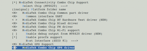
- Go to Device Drivers -> MediaTek Connectivity Combo Chip Config.
- Modify Platform folder name.
- Typing ‘insignal’.
- Select items like picture of bottom.
- Save the configuration.
- Build kernel.
$ kernel_make -j8
Android
- Modify ‘device/samsung/arndale/BoardConfig.mk’ file.
CONNECTIVITY_SOLUTION := mtk
- Build android
$ make kernel-binaries
$ make -j8
- Fusing the created images.
ADB setup on Windows
Environment
- Host OS : Windows 7 64bits
- Target Board : Arndale Board
Check VID/PID on your PC
- Boot arndale board with connecting OTG cable to your PC.
- Check new hardware in
Properties -> Device Manager>
(you can find unknown device named as “Full” where Other devices tree. Or maybe you can find different name. we will assume this unknown device’s name is “Full”) - Computer -> Properties -> Device Manager -> Full -> Properties > Details
- Change dropdown property “Hardware Ids”, you can get Values like belows
USB\Vid_18d1&Pid_D002&Rev_0226
USB\Vid_18d1&Pid_D002
...
 Means, VID: 18D1, PID : D002
- These IDs can be changed by board or PC.
Modify inf file
- Add (or Modify) your VID/PID on downloaded usb driver file from
- Unzip downloaded usb driver.
…
[Google.NTamd64]
; HTC Dream
%SingleAdbInterface%             = USB_Install, USB\VID_0BB4&PID_0C01
%CompositeAdbInterface%     = USB_Install, USB\VID_0BB4&PID_0C02&MI_01
%SingleBootLoaderInterface% = USB_Install, USB\VID_0BB4&PID_0FFF
; HTC Magic
%CompositeAdbInterface%     = USB_Install, USB\VID_0BB4&PID_0C03&MI_01
…
- Add ID that gets from section i after this line, like below.
; Android USB Gadget
%CompositeAdbInterface%     = USB_Install, USB\VID_18D1&PID_D00201
%CompositeAdbInterface%     = USB_Install, USB\VID_18D1&PID_D002
Install USB driver
- Select Update Driver Software from Device Manager
- Select Browse my computer for drvier software
- Insert (Browse) the location where driver software save on your computer.
Information
For more information, please visit below site. We will update for your information.

